차량용 전원변동 시험기 | SG-7040 series
관련링크
본문
품명 : 차량용 전원변동 시험기/ Power Supply Voltage Fluctuation Simulator
모델명 : SG-7040 series
ISO16750 및 각 자동차 메이커에서 요구되는 DC 전압의 변동 파형을 재현 할 수 있습니다.
제품의 구동 전원 (+ B / ACC / IG1 / IG2 등)을 최대로 4ch의 동기를 취하면서 변화시킬 수 있습니다.
ISO16750 규격에 준거
파형 연산 회로를 탑재하여 고해상도 · 고정밀도를 실현
최대 4ch의 변동 시험에 대응
오실로스코프에서 획득 한 실차의 변동 파형을 재현 할 수 있습니다.
Test에 필요한 인력과 시간을 감소 할 수 있는 자동화 시스템을 구축 할 수 있습니다.
사양
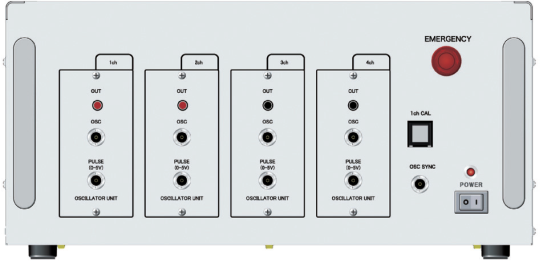
Muti-sequential Oscillator SG-7040
| Parameter | Specifications |
| Channel | 1channel - 4channels (Max.4 channels) |
| Trigger output for Oscilloscope | BNC connector/ 0-5 Active low |
| Set the desired point as the trigger point with the waveform creation software, and monitor generated waveforms with the external trigger function of the scope | |
| Waveform generating method | Sampling waveform output based on partial waveform memory and DSP circuit output CSV data |
| Output voltage | 0.00 to ±6.00V |
| Output current | 5mA max. |
| Output impedance | 50 ohm |
| Resolution (Setting) | 0.01V |
| Resolution (Output) | 0.732 mV |
| Offset voltage | ±6.0 V |
| Frequency response characteristics | 150kHz max (±6.00V amplitude sine wave) |
| 150kHz max (±6.00V amplitude rectangular wave) | |
| Frequency accuracy | ±20ns+50ppm (over the entire frequency range) |
| Rise time/Fall time | Less than 100ns (0±1.00V swing) |
| Slew rate | 20V/µs |
| Synchronization accuracy | Adjustable up to 1,000,000µs, at a step of 1µs to compensate differences in response time of the amplifiers connected |
| Synchronization accuracy of less than 1µs at the outputs of the amplifiers connected | |
| Calibration output | 1kHz 1V-p-p (for test) |
| PC interface | USB1.1 |
| Dimensions | Approximately (W)430 x (D)400 x (H)200 mm |
| Weight | Approximately 10 kg |
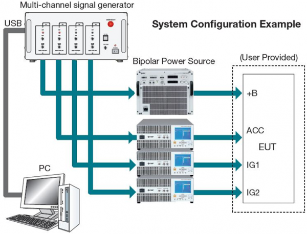
이 시스템은 기본적으로 다 채널 신호 발생기, 바이폴라 전원 및 임의 파형 생성 소프트웨어의 세 가지 요소로 구성됩니다.
적절한 바이폴라 전원을 선택하고 시험 요건에 따라 다채널 신호 발생기를 구성해야한다
1. Multi-channel signal generator
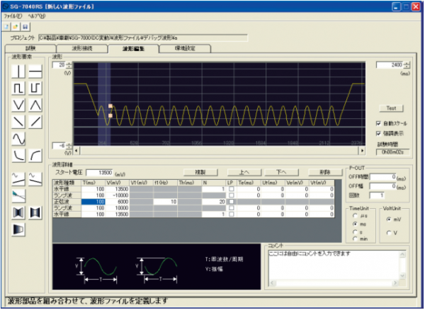
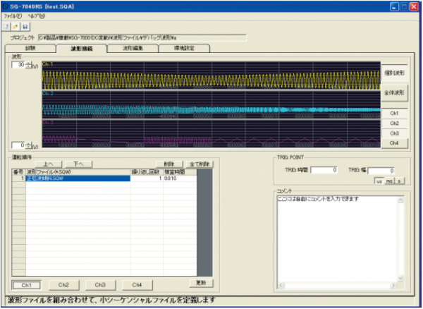
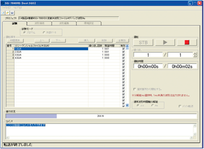
2. Arbitrary waveform creation software
3. Bipolar Power source
software
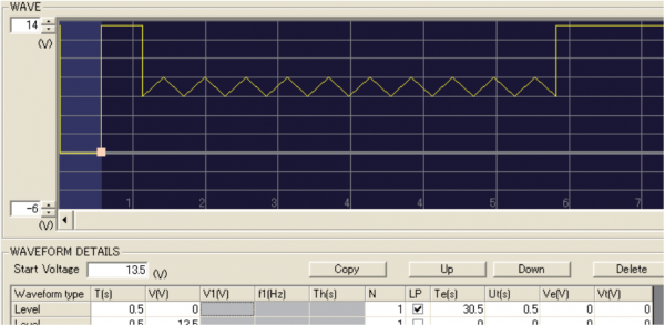
Sweep setting function
다양한 T(times) 및 V(voltages)가 필요한 긴 테스트 기간 동안 왼쪽에 자세히 설명 된 스위프 기능을 사용하여 루프 파형을 쉽고 안정적으로 생성
T(ε) = Start Te(ε) = Stop
Ut(ε) = Step N = Loop Number
LP = Loop Setting
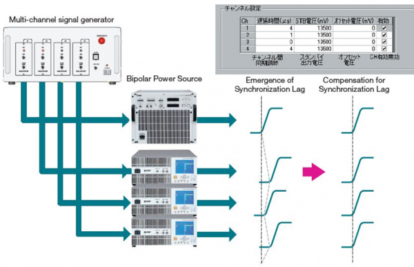
Delay set function
다중 채널 테스트에서는 각 개별 채널이 정확하게 동기화되도록하는 것이 중요합니다.
이 시스템은 연결된 전력 증폭기와의 출력 타이밍 차이를 보정하여 1μs 이하의 동기화 지연을 보장하는 반면
다른 시스템에는 유사한 기능이 장착되어 있지 않아 종종 잘못된 테스트가 발생합니다.


